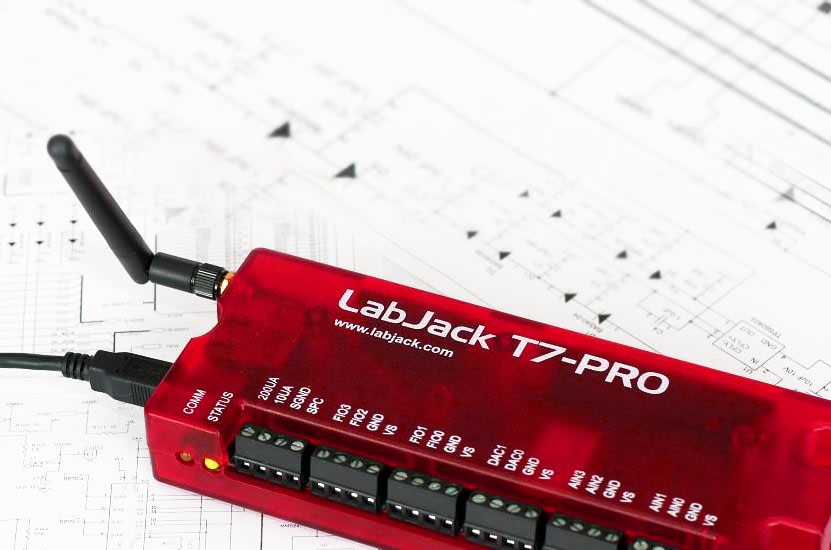
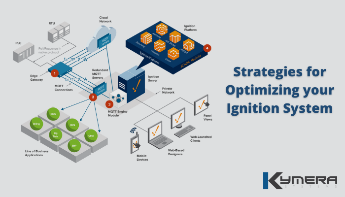
local architecture and engineering firm set out to test different building cladding and insulation approaches for their buildings; however, collecting test data turned out to be a large roadblock. How could they record data from multiple sensors at a high rate and consolidate this data without a lot of manual steps? Finding a platform that could provide a simple way to read, store and utilize data was the first step. Ignition was developed as a SCADA platform, but the capabilities it provides allow for much broader use cases. The benefits to Ignition are its connectivity, extensibility, the built in UI tools and its data management system. It is very easy to configure Ignition to store its data into MySQL and retrieve it later. The issue then became how to get the sensor data into Ignition. Since this is a small scale test, sensors that can broadcast the data using OPC or Ethernet directly would be quite expensive. The labjack UE9 device is data acquisition and measurement device that allows the user to read the temperature and humidity sensors through Ethernet. The sensors are connected to the device, which is then connected to the network. Values can be read and written to the device by sending Byte commands directly to the device, which will then process the requests and provide the requested information. Labjack has a well documented communication API, which was used to write the Ignition driver. The Ignition driver is the bridge between Ignition and the Labjack UE9 device.
Since the UE9 device is only being used to read/write sensor data, the only low level function that we implemented was the Feedback command. This command reads/writes almost all of the I/O slots on the labjack device, which is all the functionality we needed for this project. The Ignition driver will be comprised of the components in the blue box:
Communication with the labjack is done by sending a Byte Buffer to the device, and then reading the response Byte Buffer. Creating the mapping between Ignition Tags and the UE9 I/O slots was the bulk of the work. The basic flow of the driver is:
-
Create and open a socket to the specified IP address
-
While the connection is open:
-
Parse the Ignition Tags and build the Request Buffer
-
Send the Request Buffer to the UE9 device
-
Read the response
-
Parse the response into the Ignition Tags
-
The structure of the Byte Buffers are well specified, but since there is a fair amount of bit packing to build individual bytes, creating a simple, clean and easy to maintain method of doing this was not trivial. The easiest way to do this would be to explicitly build each byte bit by bit, but this would quickly bloat the code base and become very hard to extend and maintain. We tried to categorize the UE9 I/O slots into different “Tag” types – for instance the UE9 has analog inputs, digital I/O, digital to analog, counters and timers. Based on the properties of these different I/O slots, we came up with the following categories:
-
Input Tag: these are read only tags.
-
Analog Input
-
Counter
-
Timer
-
-
DAC Tag: these are the digital to analog tags, which are write only, they are never read.
-
DAC tags
-
-
Digital IO: These tags are single bits, and are both readable and writeable. These tags also have an associated “mask” tag that must be set before a value can be written.
-
Digital I/O tags
-
Once these tag objects were created, Ignition tags could then be mapped to these UE9 tag objects. This mapping is done when the device is created in the Ignition Gateway. When creating the Request Buffer, the Ignition tags are used to update the UE9 tags (by Ignition), which are then packed together according to the Labjack UE9 API. Once this structure was in place, all that was left to do was write the logic for packing the UE9 tags into the Request Buffer and unpacking the Response Buffer.
Building the Request Buffer is pretty straightforward as most of the bytes are constant; all that was required was to pack all the writable tags into their respective bytes. The digital I/O tags have a mask bit for every I/O bit which is used to determine if the value is supposed to be written to the device or not, and a bit to determine if the I/O is being used for input or output. So, for a value to be written to a digital I/O slot, it must be set as input, and the mask must be set. The direction (input or output) is set by the user through a corresponding Ignition tag. The mask is set whenever the state value is changed: when a new value is written to the Ignition state tag, the mask is automatically set to 1, and then reset to 0 after the request is set. The DAC tags required some specific bit packing to get the values into the correct byte format, but nothing tricky. Building the request buffer turned into:
-
Create the base request buffer, setting all the constants.
-
Pack the digital I/O tags
-
Pack the Analog Gains
-
Pack the DAC tags
Parsing out the Response Buffer was very similar to creating the Request Buffer. Since the digital I/O tags had to be read as well as written, the byte manipulation logic already existed from the write, so we were able to reuse a lot of that for unpacking the bytes into the appropriate Ignition tags. Since the UE9 supports high resolution analog values, each analog input was 2 bytes. Parsing these bytes out into a double was pretty straight forward:
-
Create a double and initialize it to 0
-
Read byte 1, shift it to the left
-
Or with byte 2
The counters and timers contain more bytes, but unpacking the bytes for these was the same idea: read bytes and shift to the left.
The driver allows us to create devices inside the Ignition gateway, with a few configurable properties, and takes care of mapping all the Ignition input/output tags to the appropriate UE9 input/output slots. All of the configuration information is also stored in Ignition tags, providing an easy way to calibrate and modify the UE9 device from within Ignition. Once the device is created, it will poll data from the UE9 at the specified rate; with a resolution of 12 bits, we were able to poll at ~2ms (which is pretty impressive for that much data). Our goal when we started out was 100ms poll rate, which is easily achieved when using a resolution of 15 bits or less (for this project 10 is more than sufficient).
When we showcased this driver, it met all of the criteria that we had set out at the start of the project:
-
<100ms poll rate (10 reads per second was goal)
-
Ability connect multiple labjack UE9 devices
-
Configurable from within Ignition
-
Easy to set up
-
Easy to store the data
Since the full insulation test scenario is not yet finished, we have not fully commissioned the project yet, but we are looking forward to continuing work with the client. I personally, had never used a labjack before, but can think of many different applications of the Labjack and Ignition combination.

